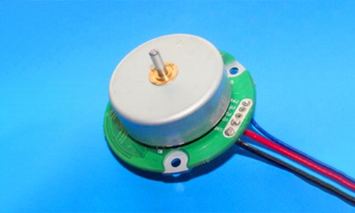
Micro reduction motor refers to the integration of reducer and motor (motor), which can also be called gear micro reduction motor or gear motor. It is basically supplied by the reducer manufacturer after integration and assembly.
The working principle of the micro reduction motor is to greatly reduce the speed through the power of the motor through the gear (or worm gear) reducer, thereby increasing the output torque of the motor to meet the needs of mechanical equipment. This kind of power transmission equipment has a core that can not be ignored - "force reduction" effect. It uses all levels of gears (or worm gears) to achieve the purpose of speed reduction. The reducer is composed of all levels of gear pairs.
The micro reduction motor mainly has the following three functions: speed reduction: the motor speed reaches the required speed through the reduction gearbox, that is, the output speed; Increasing torque: under the same power condition, the slower the output speed of the gear micro reduction motor is, the greater the torque is, and vice versa; Change the transmission direction: for example, bevel gear micro reduction motor can transmit torque at 90 degrees vertically. Among them, the speed provided by the reducer is low and the torque is large; At the same time, different reduction ratios can provide different speeds and torques. Different industries usually use different power DC micro reduction motors, and generally adopt customized power design mode. (Compared with the ordinary motor, the micro reduction motor has a matching gear reducer.)
Because of its high integration, the micro reduction motor has many excellent characteristics: compact structure, small length and small volume; Fine classification of transmission ratio, wide selection range and wide speed spectrum; Superior performance, low energy consumption, mechanical efficiency of gearbox up to 94%; Strong universality, convenient disassembly and maintenance, low maintenance cost; New sealing device, good protection performance and strong environmental adaptability; From the internal structure, (from right to left) the planetary reducer is roughly composed of motor side (input side) bearing, motor side flange, input shaft, planetary gear set, output shaft, output side (load side) flange and load side bearing.
In the middle of this series of components, there is the core transmission component that any planetary reducer must carry:
planetary gear set. In the structure of planetary gear set, there are several gears around a central gear on the inner ring of the reducer housing. When the planetary reducer is running, with the rotation of the central gear, several gears around will also "rotate" around the central gear. Because the layout of the core transmission device is very similar to the way the planets in our solar system move around the sun, the reducer is called "planetary reducer".
The central gear, usually called the "sun gear", is driven by the input servo motor through the input shaft. The multiple gears revolving around the sun gear are called "planetary gears". One side of the gear is engaged with the sun gear, and the other side is engaged with the annular internal gear ring on the inner wall of the reducer housing, which carries the torque power transmitted from the input shaft through the sun gear, and transmits the power to the load end through the output shaft. In normal operation, the track is an annular inner gear ring on the inner wall of the reducer housing.

